
ULTRA MK2 Midi Mapping Explained
MIDI Mapping using an APC40 MK II or APC Mini MK II
The Ultra MK2 is capable of being controlled directly using an APC 40 MK2 or an APC mini MK2 (others will be added TBD.) connected to the USB port on the rear of the unit.
In order for any MIDI mapping to be saved, an SD card must be inserted with the correct path to the settings folder present on the card. The MIDI mapping files saved to the card are located here: Lasercube/settings
Separate mapping files are saved for each MIDI device type, and also for each MK2 control mode.
The MIDI mapping files are also saved in JSON file format which is human readable text, so the user can also edit these files manually using a text editor if required.
Enabling USB MIDI
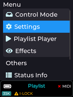
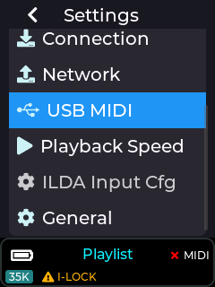
In order to use any of these MIDI devices, the USB must be enabled by going to the Settings ->USB MIDI menu.
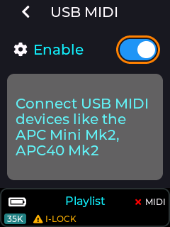
Note: USB MIDI does NOT operate when the unit is in LaserOS / ArtNet / DMX control modes, as these modes are controlled using alternate communication protocols.
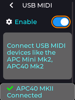
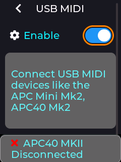
If a compatible device is detected on the MK2 USB port then the status bar will briefly show an updated connected status, and unplugging a device will show the disconnected status as shown above. The status bar will also show a green tick or a cross next to the MIDI label on the RHS of the status bar.
MIDI Mapping a Slider Control
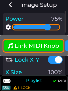
To map a slider in the menu to an APC dial or fader control, single press on a slider to enter edit mode, then long press to bring up the context menu, and then select “Link MIDI Knob” as shown below.
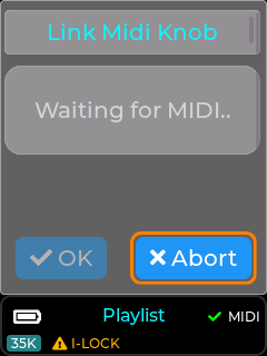
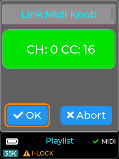
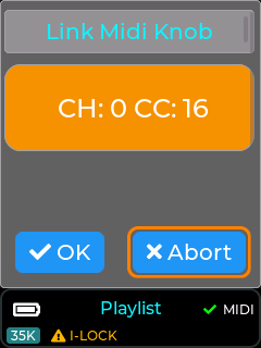
Once “Link MIDI knob” is selected, the MK2 will wait for the user to turn or move a control on the APC. Once a control is moved then the associated MIDI channel and CC number will be captured.
If the MIDI channel and CC chosen by the user is already assigned to another control then the MIDI info will be shown in orange instead of green.
If the user accepts this APC control while the MIDI status is orange, the previous function will be un-mapped and re-assigned to the current UI slider.
Almost all sliders in the MK2’s menu UI can be assigned to an external APC Dial or Fader.
Note: Faders on an APC40 are absolute controls and will always override the MK2 slider value when moved, unlike APC dials which are relative adjustment control with no physical end stops.
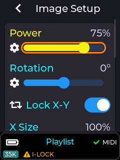
Once a slider from the MK2’s menu UI has been assigned to an APC control, the menu UI will update its slider to a yellow colour instead of blue as shown in the image below. Any movement of the assigned APC control will now also move the slider on the MK2 menu.
If the slider was assigned to a dial on the APC40 MK2 then the LED ring on the APC dial will also reflect the slider’s current value, and editing the slider on the MK2 menu UI will also update the APC’s led ring as they are always kept in sync with each other.
The image below shows how an APC dial will look once mapped to a MK2 slider element.
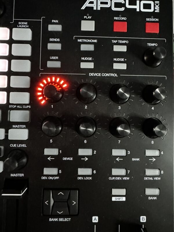
Note: When an APC dial is un-linked from a MK2 UI element, the LED ring will go off.
Un-mapping a Slider Control
To remove a previous MIDI mapping from a slider in the MK2 menu UI, edit the control by short press on the slider to enter edit mode, then long press to bring up the context menu, then select “unlink MIDI Knob” option.
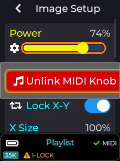
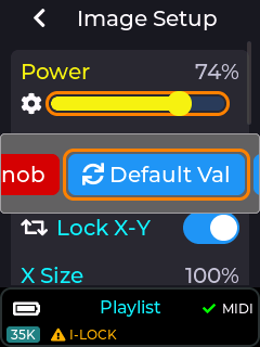
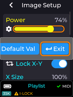
The images above show all the options available on the slider pop-up context menu, including the un-link option. The “Default Val” button will return the currently edited slider to its factory power-on default value, and the “Exit” button closes the context menu without performing any other actions.
Once the unlink option has been selected on the context menu, the control will return back to a blue colour indicating that it is no longer associated with any external MIDI control.
MIDI Mapping a Button Control or Switch
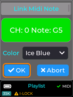
Buttons and Switch elements in the menu UI can also be mapped to an APC button by highlighting the element on the MK2 menu UI, and then long pressing to activate the context menu. Once the context menu is activated you can select the “Link MIDI note” option, then press a control on the connected APC, and then assign a LED colour using the colour drop down. Un-Linking is done by long pressing on a UI element and selecting “Unlink” from the context menu.
MIDI mapped buttons / switches will also show in yellow instead of a blue colour.
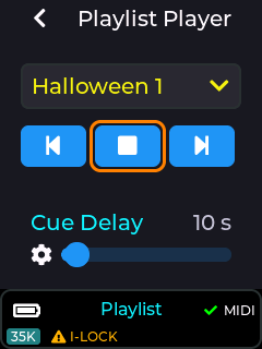
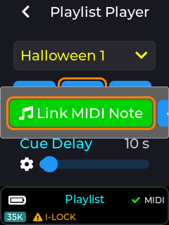
The images below show the MK2 in playlist control mode with it’s play button MIDI mapped to an APC button. If the APC button selected has an RGB LED associated with it then the button will light up on the APC with the colour selected from the colour dropdown.

MIDI Mapping a Drop Down control
Most of the drop down UI controls within the MK2 menu UI can be linked to a button on a connected APC MIDI controller. These include the currently selected playlist drop down, and also the laser show drop down when in laser show control mode.
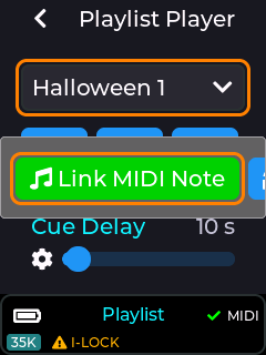
To MIDI map a drop down you will firstly need to select an item from the drop down that you wish to assign to an APC button, then long press on the drop down in order to bring up the context menu.
Once the context menu is visible you will be able to assign the currently selected item from the drop down to a button on the APC using the “Link MIDI Note” button. Previously linked items can also be un-linked using the same procedure of selecting the drop down item and then long pressing to bring up the context menu, followed by selecting the “UnLink MIDI Note” option.
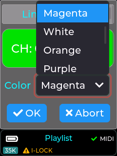
With an APC40 or APC Mini connected, there are a total of 15 different colours selectable during the MIDI mapping process.
Note: Some APC buttons do not contain an RGB LED, so consult the relevant documentation for your APC device to determine which APC buttons can have an RGB colour assigned. If an APC button only has a single LED colour, then only select the first colour from the colour drop down.
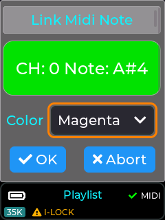
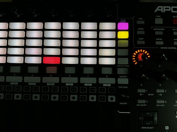
The drop down UI element will now be shown in yellow, indicating a mapping to an APC button, and the APC button (top right) will change to the selected colour (Magenta in this example).
Default APC40 MK2 MIDI mapping
The default MIDI mapping for an APC40 MK2 is shown below, and is provided with the factory SD card image.
This mapping can be changed by the user if required using this guide.
Items in blue are relevant when in playlist control mode, and items in red are part of the effects provided when in playlist or visualizer control mode, and items in yellow are global device adjustments linked to items within Settings→Projection→Image Setup.
